Click
to hide the solution
The hole should be drilled through
the neutral layer, the middle mark.
If it is drilled in the layer
where the wood fibers are under tension it will significantly weaken the
area and cause the branch to fall. If it drilled in the area where compression
is taking place the hole will be crushed.
|
|
|
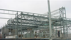
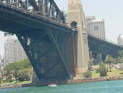
| As we read earlier,
steel girders undergo stresses of both compression and tension (stretching).
The Sydney Harbour Bridge is constructed with steel girders as are the frames
of many large buildings. Steel girders are similar to solid steel beams
but with a chunk of steel removed from the middle on each side giving it
its characteristic "I" shape.
|
 |
|
|
Now
the "I" shape of the steel girders, at first, appears strange.
Surely a solid beam of steel is stronger than the "I" configuration.
Surprisingly the "I" shaped girder is nearly as strong as a solid
steel beam of identical dimensions. The advantage of the "I" beam
configuration is that it is light. If all bridges or frames were constructed
of solid steel beams the mass they would have to support would be a severe
handicap. |
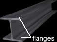
| Most
of the material in a steel girder is concentrated on the top and bottom
parts, called the flanges. The piece of steel connecting the bottom
and top flanges is known as the web. A steel girder placed horizontally
experiences both tension and compression as it supports a load. The top
flange experiences compression forces while the bottom flange experiences
tensile forces. The web between the top and bottom flanges experiences little
stress. |
| The
stress applied to a particular surface of a structure is given by the expression
on the right. If a given force is spread over a large surface area then
the stress on the structure is less than if the force is concentrated over
a small area.
|
|
| Consider
a horizontal girder supporting a load with the cross-section shown on the
right. The red line indicates tension. Notice that the flange on the bottom
has a greater surface area than the flange at the top. Tensile forces are
spread over a wider area and the stress on the bottom flange is minimised.
|
|
| As we
read earlier, materials have a greater compressive strength than tensile
strength. They can cope well with high compressive forces but not with high
tensile forces. Increasing the surface area of the bottom flange spreads
the force over a greater area and reduces tensile stress. The girder pictured
above can withstand greater loads than the one pictured below. |
| Explain
why this girder can withstand less load than the girder pictured above. |
|
The
diagram on the right shows the cross-section of 4 horizontal girders.
a) Which girder can support the least load?
b) Which girder can support the greatest load?
c) Girders a) and b) were subjected to a steadily increasing load. Which
girder will fail first and why?
Girders c) and b) were subjected to a steadily increasing load. Stephen
predicted that girder b) will cope with twice the load placed on girder
c). Is he correct? Explain.
|
|